Total head on pump consists of three components.
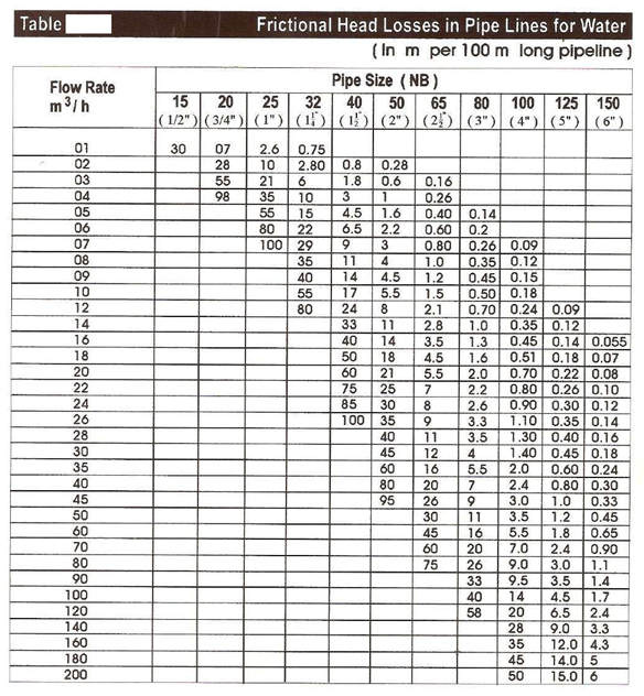
Refer below table to calculate frictional head loss
Brief definition of pump head and system head
There are two possible conditions.
More often the term NPSH is misinterpreted as suction lift or suction head. This is not correct. The definition of NPSH is the absolute energy (Head) required to push the liquid into the impeller eye. If this is not provided, then the pressure at the eye of the impeller drops below the vapour pressure of the liquid and cavitation takes place. This ultimately deteriorates the performance of the Pump. The available NPSH can be worked out by the use of following formulae. See that the available NPSH is more than the NPSH required. (Specified by the Pump Manufacturer) NPSH = Ha ± Hst – Hvp – Hf.
Where Ha = Atmospheric Pressure expressed in terms of liquid column. Hst = Negative / Positive Static Head. Hvp = Vapour Pressure of the liquid expressed in terms of liquid column Hf = Frictional Head losses in suction pipeline.
Suction Lift is a negative head (Liquid level below Pump Centre Line), the Pump has to overcome. Whereas the NPSH is net positive suction head available to the Pump at Impeller eye. If available NPSH is more than required NPSH (Specified by the Pump Manufacturer), then Pump will satisfactorily.
Pressure developed and power consumed by the Pump is directly proportional to the density of the liquid. This is explained as under. If a Pump develops 1kg / cm2 pressure and consumes 1kW power for a density of 1g / cm3 then pressure developed by the Pump for another liquid of a density of 1.5g / cm3 will be 1.5kg / cm2 and power consumed will be 1.5kW.
Higher viscosity of the liquid will have an effect on parameters like Head, Rate of Flow and Efficiency. The conversion factors can be derived for theses parameters from the graphs provided by Hydraulic Institute.
Atmospheric pressure is dependant upon the altitude. Higher the altitude less the atmospheric pressure. Therefore available NPSH will get reduced at higher altitudes. This has to be compensated by providing higher static head on suction side of the Pump.
Vapour pressure value will have direct effect on the available NPSH. Higher the vapour pressure lesser the NPSH available. This has to be compensated by providing higher static head on suction side of the Pump.
All the performance parameters such as Head, Rate of flow and Power of the Pump will change due to change in speed. The changed parameters can be worked out by using following formula.
Where a) Q1, H1, P1 are known parameters at known speeds N1. b) Q2, H2, P2 are parameters to be calculated at desired speed N2.
All the performance parameters such as Head, Rate of flow and Power of the Pump will change due to change in impeller diameter. The changed parameters can be worked out by using following formula.
Where c) Q1, H1, P1 are known parameters at known impeller diameter d1. d) Q2, H2, P2 are parameters to be calculated at desired impeller diameter d2.
N.B.: These conversion formula generally hold good for Pumps having Radial Flow Impellers. Do not use these formula for mixed flow and action flow impellers.
Many people think that Pump will not work if it is run in reverse rotation however it is not true. If the Pump is run in reverse rotation it will develop Approx. 80% rate of flow at 65% head and will run at 50% of the rated efficiency. Thus the performance of the Pump deteriorates substantially and hence not advisable to run the Pump in reverse direction.
Higher size motor rating will not change the performance of the Pump as the speed of the motor is same. Hence it is not advisable to use higher size motor rating of the same speed to improve the performance of the Pump